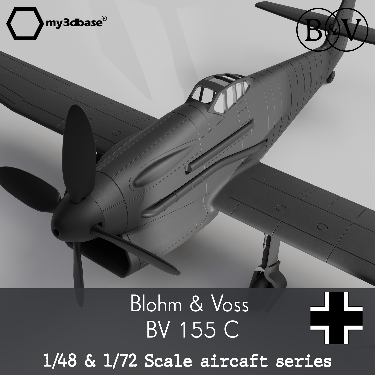
BV 155: The high altitude interceptor
From 'B' to 'C' version
• • •
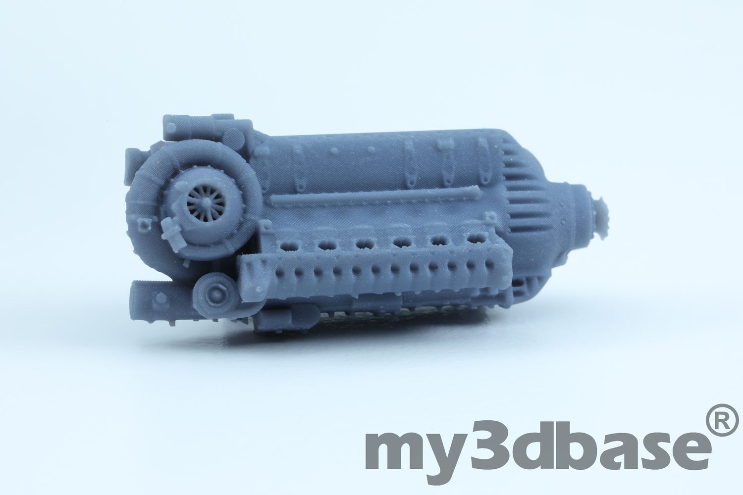
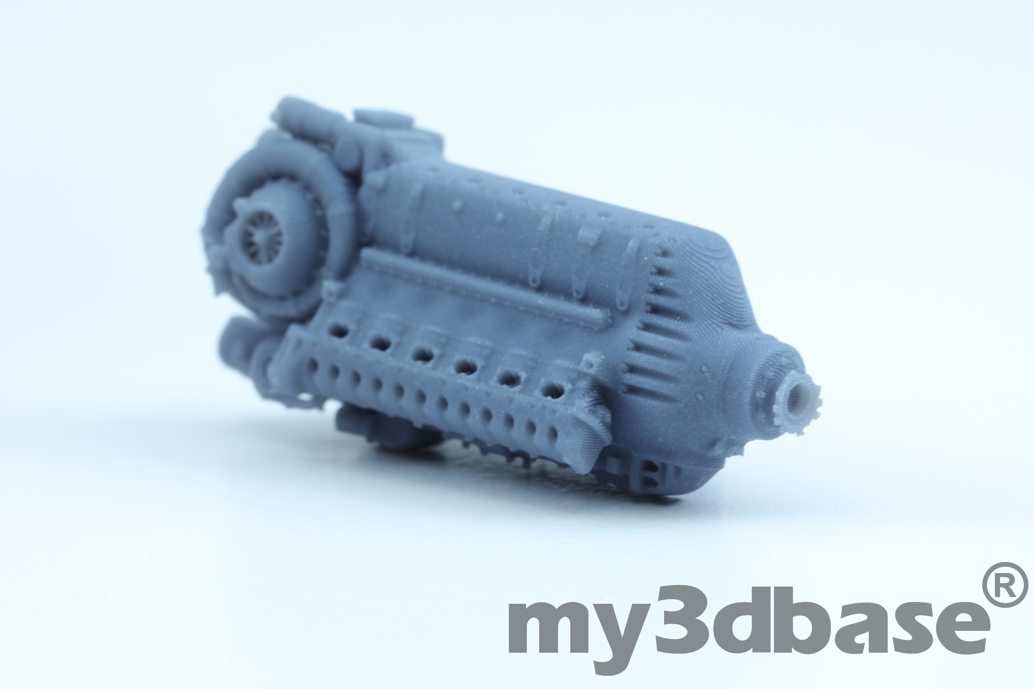
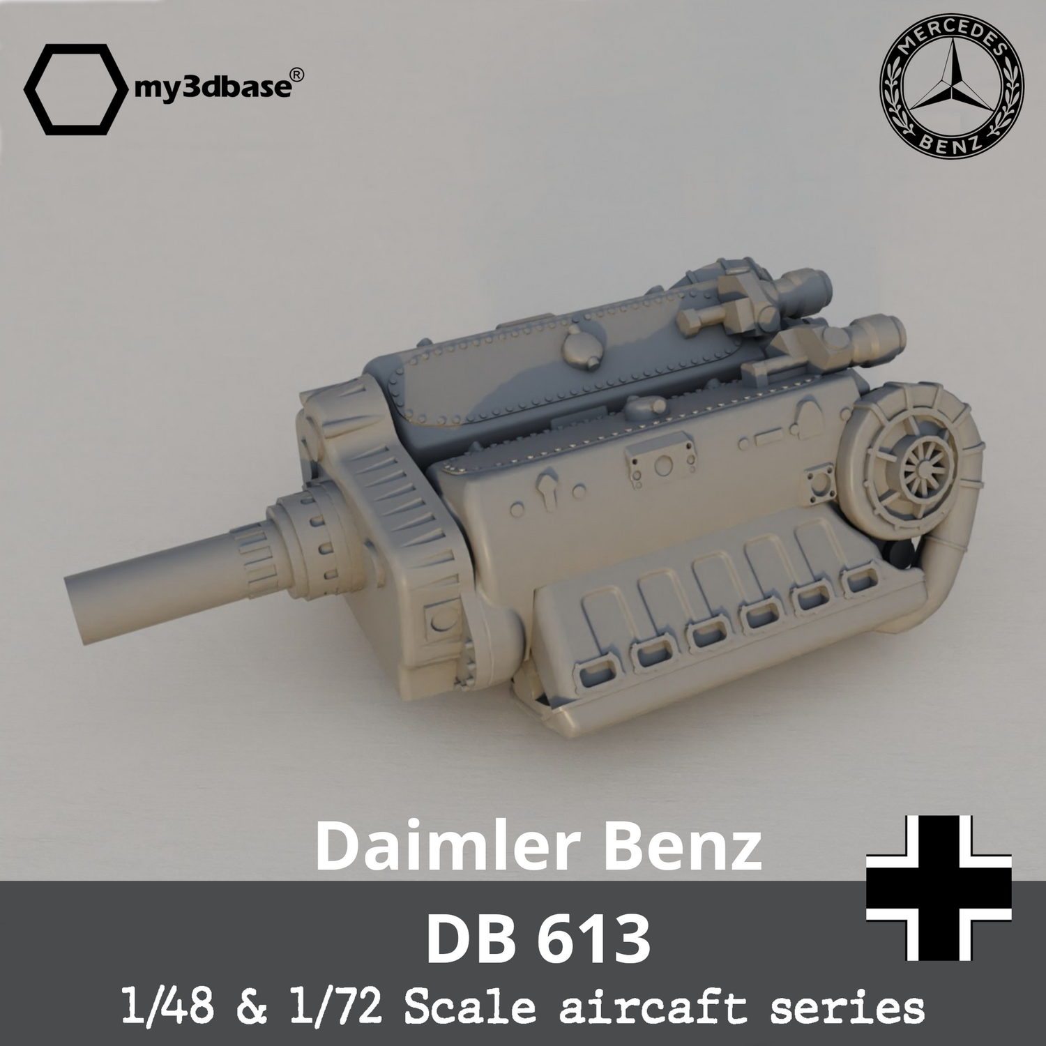
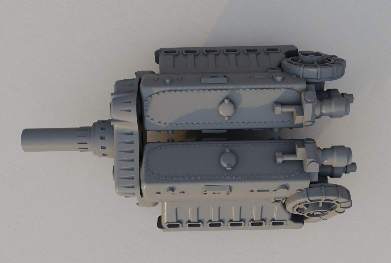
The overall development of the BV 155 involves plenty of politics and also miscommunication between the involved companies, mainly Blohm & Voss and Messerschmitt. This is well described in Dan Sharp's book, 'Secret Projects of the Luftwaffe 2, Blohm & Voss BV 155. A prototype of the 'B' version, with wing mounted radiators, was built and tested late in WW2. Apparently, B&V was not entirely happy with the design and started to design a new version of the aircraft, the type 'C'. Characteristic for this version is a central intake at the nose of the fuselage, that serves as air intake for both the engine coolers and for the TKL 15 turbo charger. The Hirth TKL 15 supercharger was a vital aspect of the high altitude interceptor, since it would provide sufficient oxygen to the engine even at higher altitudes. It was positioned behind the pilot and would feed compressed air back into the DB 603 via a long pipe situated outside the fuselage skin. Exhaust gases from the engine would spin a turbine that in turn would run the compressor transporting air at higher pressure back to the engine.
There is only limited information available on the 'C' version. But overall the fuselage and wing were similar in design to the 'B'. The main difference was, as described, the shape and size of the air intakes. The underlying idea by B&V was most likely to improve the overall design without having the change too much of the structure. Since that would have meant all new tooling and design work. With that assumption, a lot of the available information on the 'B' version can hence be assumed to also be representative of the 'C' version.

Of the 'C' variant, a wooden mockup and several fuselage components were constructed. But no complete aircraft. The overall shape of the aircraft is assumed to be identical to the 'B' variant, apart from the chin mounted air intake.
Hirth TKL 15
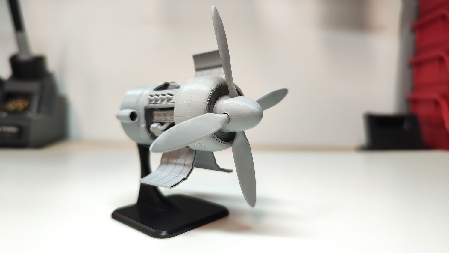
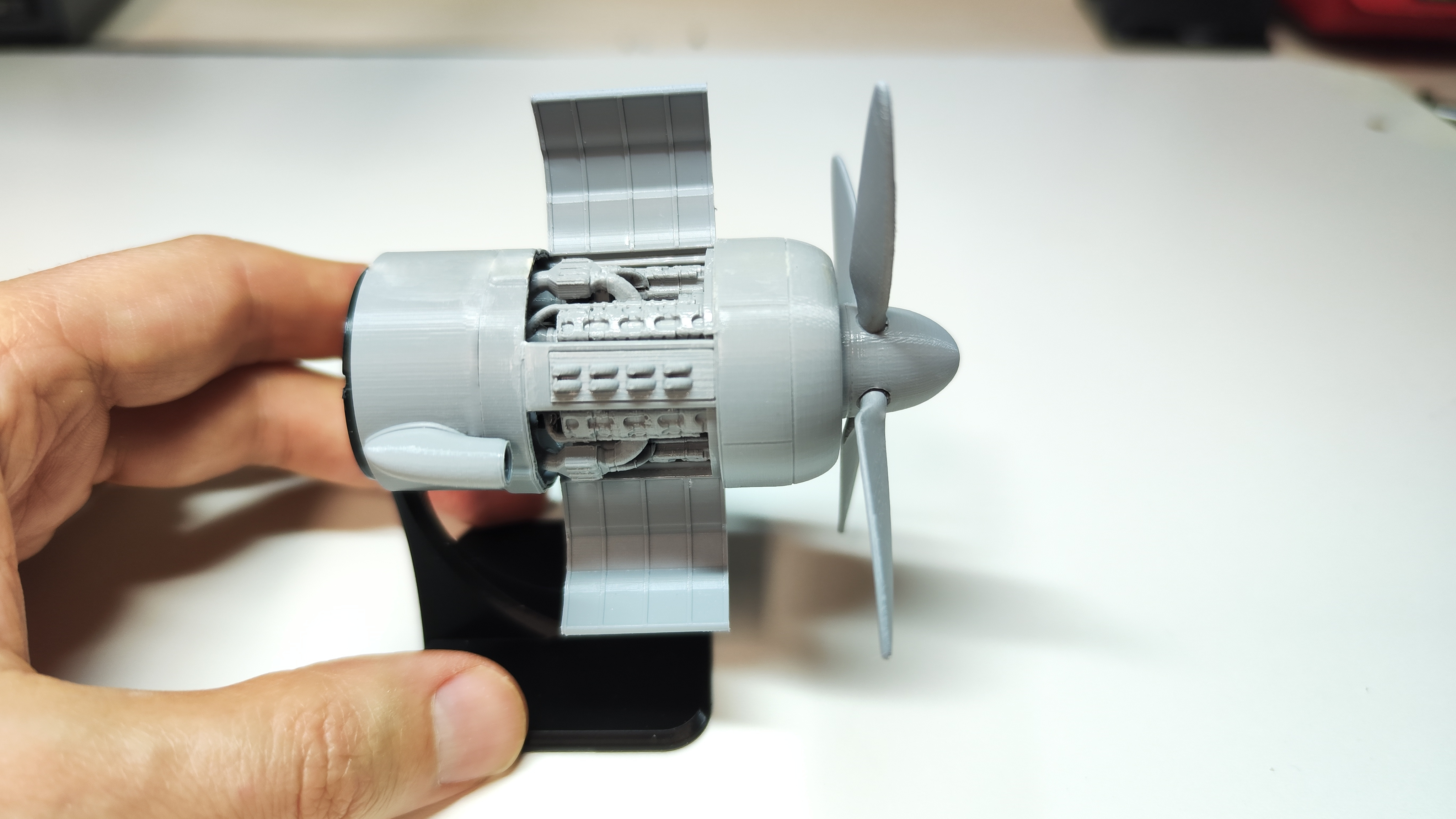
The Hirth TKL-15 supercharger was a large piece of equipment and a central aspect of the aircraft. Two vertical intakes would feed exhaust gases through the turbine of the TKL-15. Compressed air from the compressor would exit from a pipe at the top.

By compressing the air, its temperature will also be increased. So it needs to pass through an intercooler on its way back to the engine.

A tubular frame would hold the TKL-15 in place in the rear of the fuselage, see image below (image courtesy Tom Fey). It is unclear if the frame also was part of the main load path to support a stressed skin design. In any case, the frame would provide the required attachment points for the installed subsystems.

It is believed that the TKL-15 carried the internal designation 9-2279, as shown in the image below.

Below is a cross section drawing of the device. The turbine could be bypassed by opening a control flap (ger. Regelklappe).

The image below depicts the TKL-15 in a test stand.

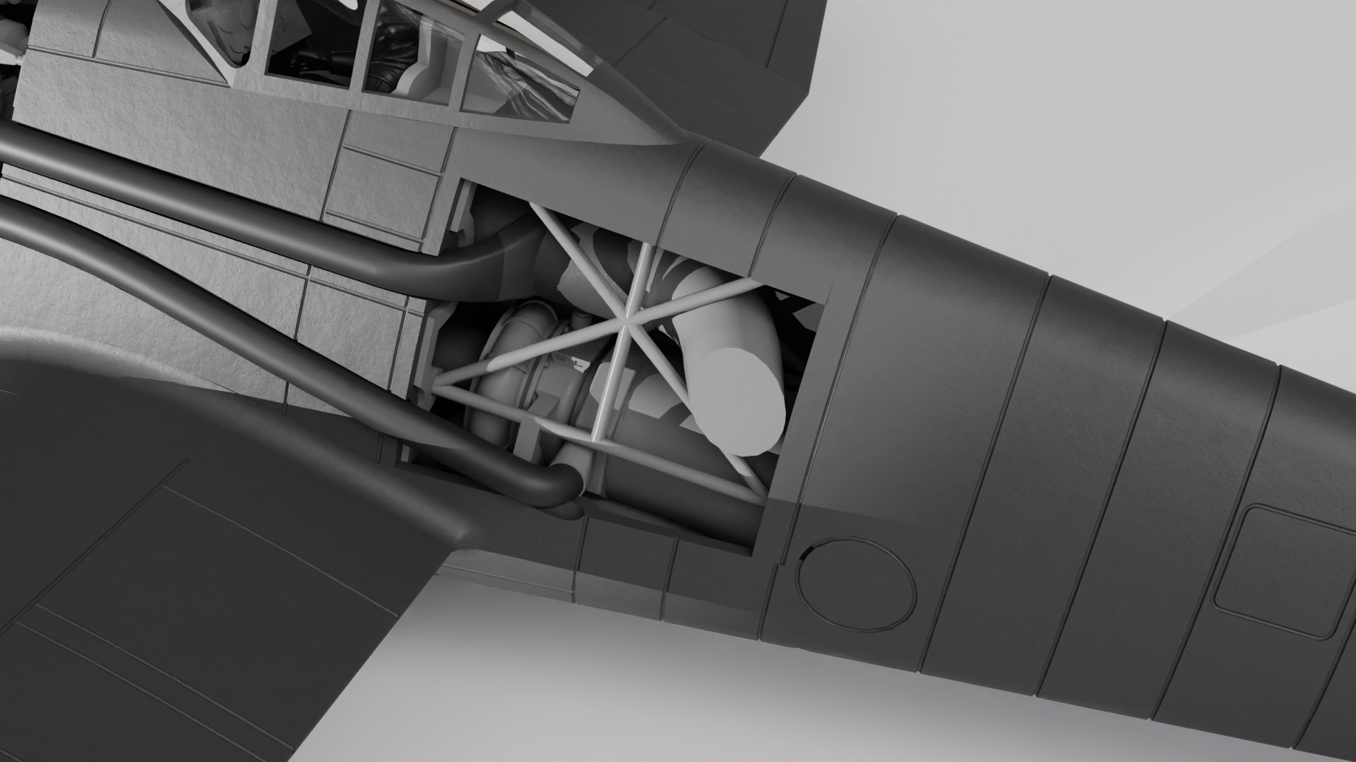
The image below depicts the mockup of the BV 155 B, with a view from the rear of the fuselage. Hatches to the turbo charger compartment have been opened, granting access to the systems located here. A tubular frame is installed, most likely in order to provide attachment points and also to transfer loads between the front and rear of the fuselage. Since the hatches have interrupted the stressed skin load path of the fuselage.

A close up of the turbo charger compartment. B

The radiator installed in the chin intake of the aircraft featured exhaust slats that would control the mass flow of the incoming air that would pass through the heat exchangers. A certain amount of air was redirected to the rear of the aircraft with a splitter plate to feed the supercharger, see image below (source). So in contrast to the 'B' version, the 'C' would combine air for the turbo charger and heat exchangers into a single intake, leaving the wings unobstructed.

A cross section of the 155 'C' was published by Monogram, see below. These were prepared by Justo Miranda. What source material was used is unclear at this point. Compressed air exits the compressor that is below the exhaust level of the engine. It is redirected upwards the engine air intake, passing through an intercooler. Exhaust air of that intercooler exits the upper exhaust pipe on the starboard side of the aircraft. The lower exits on both sides of the fuselage are exhaust gas exits of the turbine. The larger one is used for the turbine and the smaller one as a direct bypass exhaust from the engine.

Access hatches for the engine are displayed in the image below. Obviously, for the C type, access from the bottom would be blocked by the air intake.

Main landing gear side view as designed for the BV 155 B, see image below. It would retract outward below the wing mounted radiators. That is not an option for the C. Here the landing gear needs to retract into the fuselage.

Main landing gear front view. It says 'Federstrebe (spring strut) from Ju 87 D-6' in writing.

Exhaust gas and compressed air pipes on the starboard side of the surviving BV 155.

Wing underside.


Rear fuselage.

The only surviving sample in storage.

Below is a picture of the engine compartment with open access hatches.

BV 155 B cockpit and instrument panel.


Main Sources:
- Secret Projects of the Luftwaffe: Blohm & Voss BV 155 Dan Sharp
- Höhenjäger Baubeschreibung BV Januar 1944
- MONOGRAM CLOSE-UP 20: BLOHM & VOSS BV 155, Thomas H. Hitchcock
- Thomas Fey
• • •