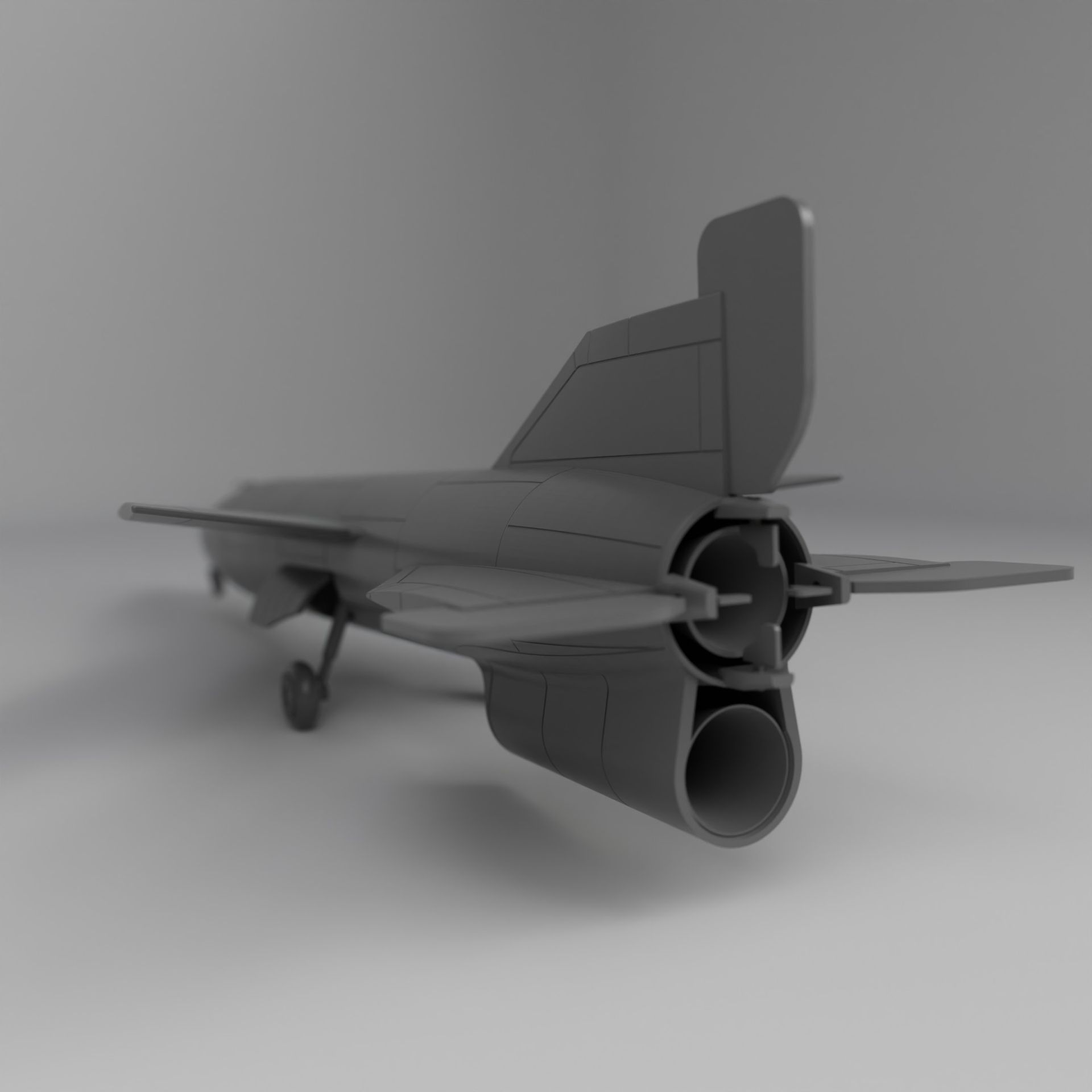
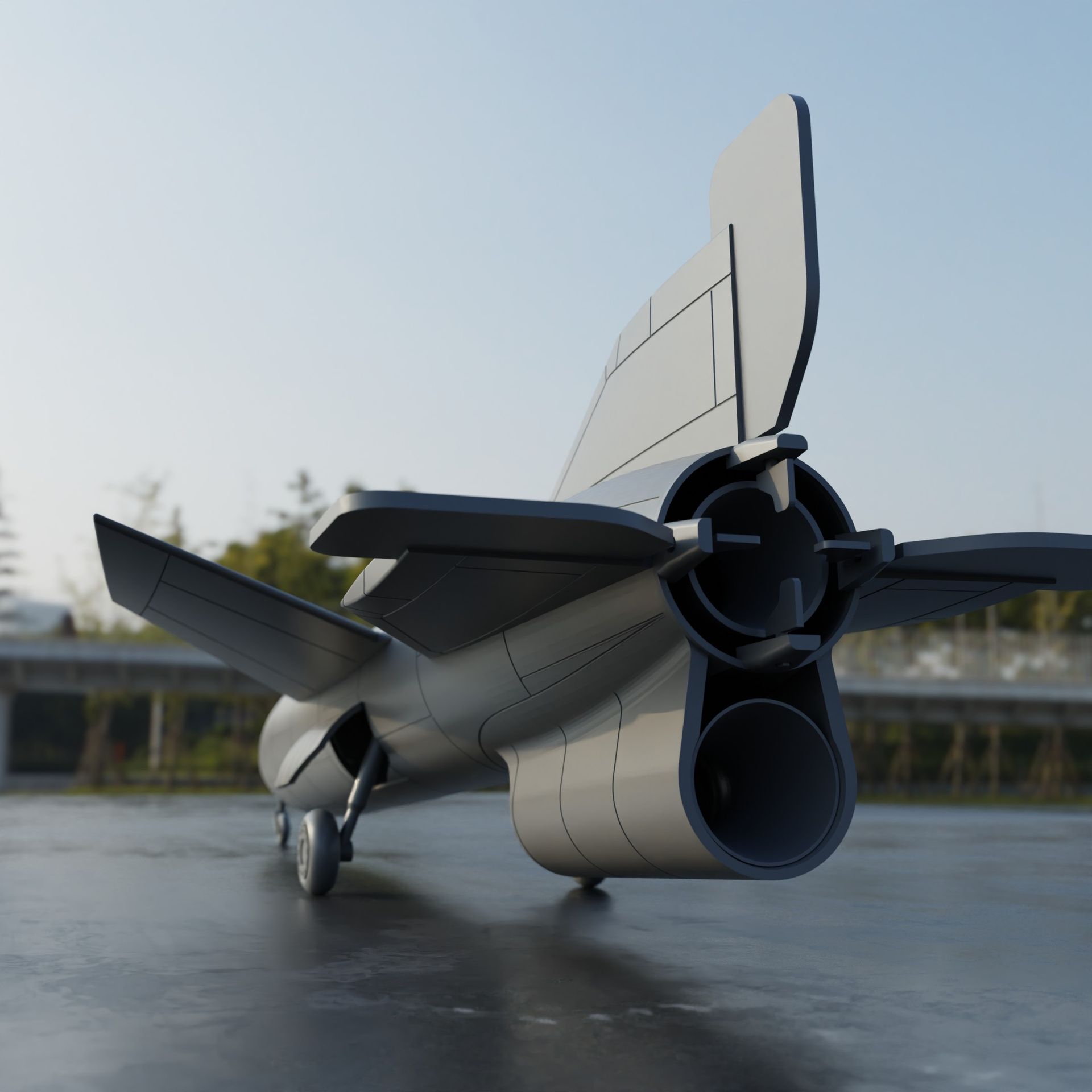
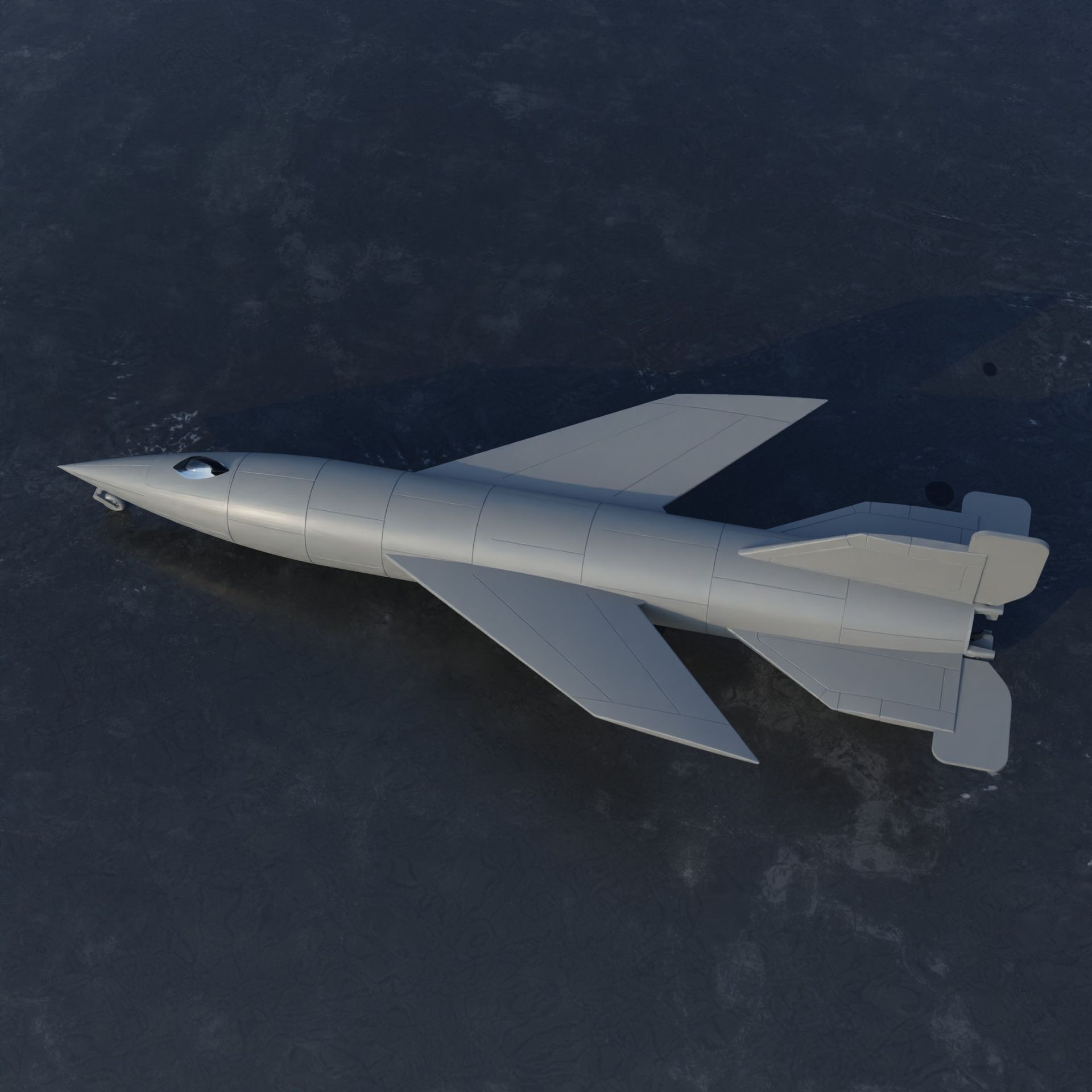
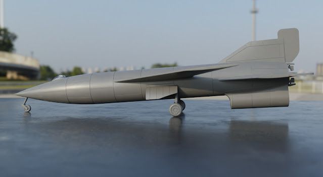
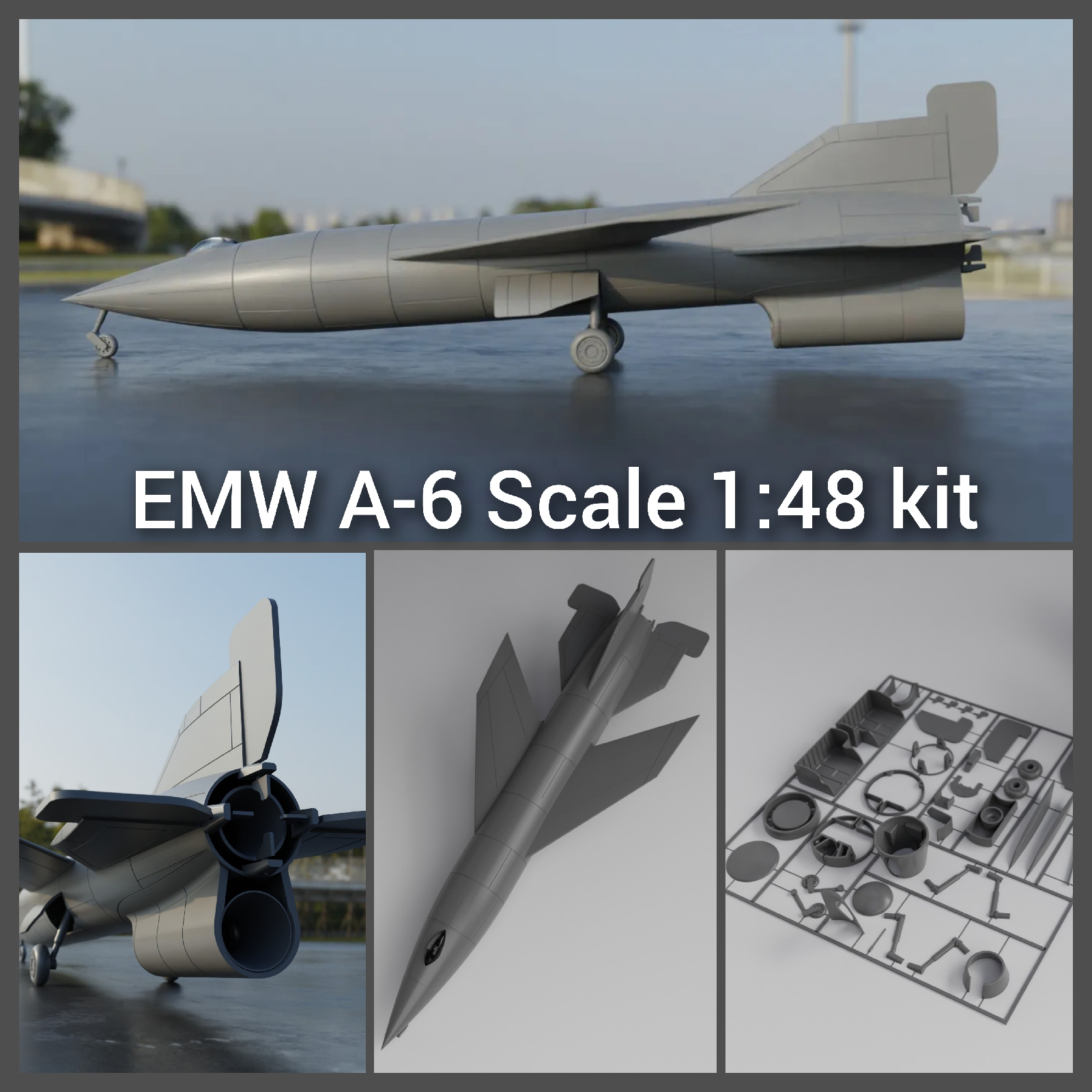
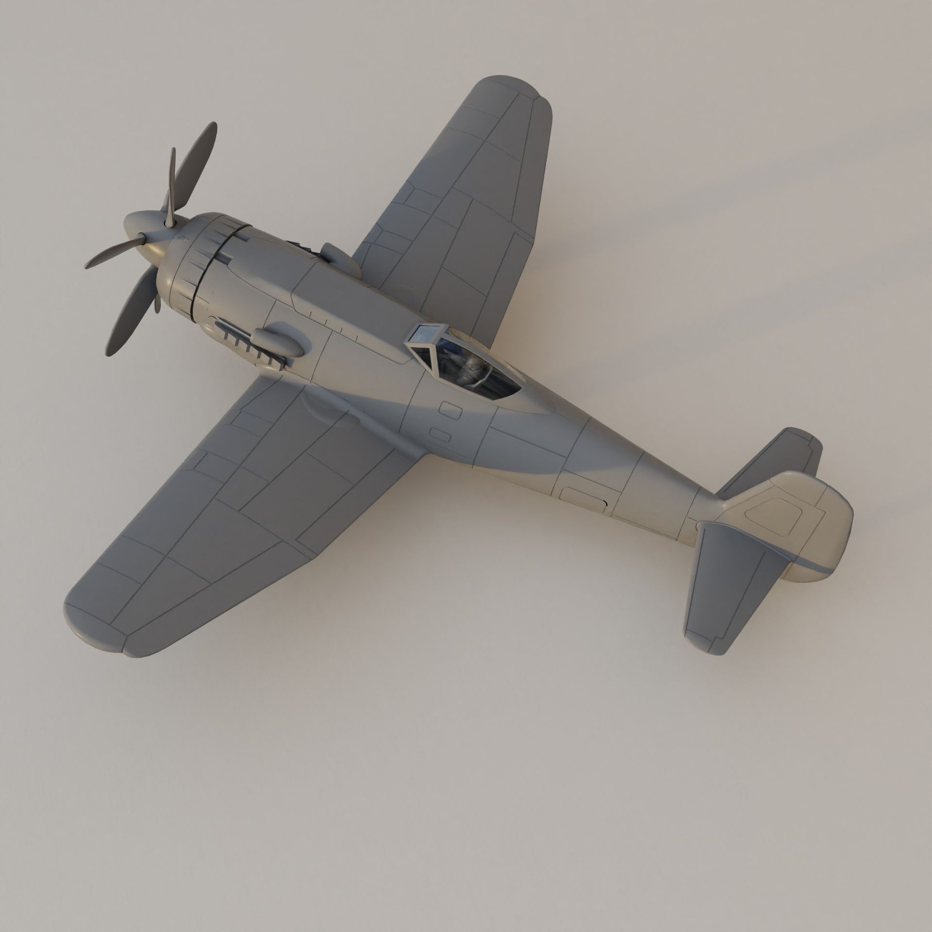
EMW A-6 model kit scale 1:48
The EMW A-6 looks definitely cool enough to justify making a model kit for it. And as far as I know, there is no 1:48 scale model kit on the market currently.
Some information from the www.nevingtonwarmuseum.com:
The A4b, manned as an aerodynamic research aircraft, the A9, as an intercontinental bomber and the A6, as a photo reconnaissance aircraft operating at great height and speed.
Actually, the military application of these scientific research programs were emphasized in order to obtain the necessary resources given the wartime circumstances.
The A6 could have been a hypersonic research aircraft, equipped with an auxiliary "Ramjet" engine, which could only be started at very high speeds.
First, here is some data:
Purpose:
‘Supersonic research aircraft
Wings:
Metal structure and skin
Fuselage:
Metal structure with metal skinning covering the nosewheel, the pressurized cockpit, the methyl alcohol tank, the gasoline tank (Br-Stoff) for the turbo-ramiet engine, the under- carriage wells and the payload (instruments, cameras). Also contained in the fuselage are the tank for the liquid oxygen, the rocket motor and the combustion chamber.
Tail Section:
Metal structure with metal skinning, plus small guide vanes in the rocket nozzle. The ventral fin normally installed on the A4 and A4b could be deleted to accommodate the turbo ramjet engine.
Undercarriage:
Tricycle undercarriage
Power Plant:
One EMW rocket producing 27 500 kg of thrust and acceleration up to 6g. One turbo-ramjet engine of unknown type and performance.
Fuel:
A-Stoff (liquid oxygen) and M-Stoff (methanol)
Wingspan: 6.33 m
Length: 15.75m
Height: 4.07 m
Maximum diameter: 1.73m
Maximum speed: 2.900 kph
Service ceiling: 9500m
The main landing gear bay (MLG) is positioned between the two main tanks. And it is very cramped. Making the leg fit with an appropriate kinematic was not easy. Naturally, this would have an effect on the size of the tanks because the space has to be provided for. A reasonable solution to the problem would maybe be, to lengthen the fuselage in order to counteract this disadvantage. Additionally, the fuselage will need to sustain loads and impacts from landing. Something the standard A4 fuselage is certainly not designed for. In particular with regard to the direction of load being almost perpendicular to the fuselage.
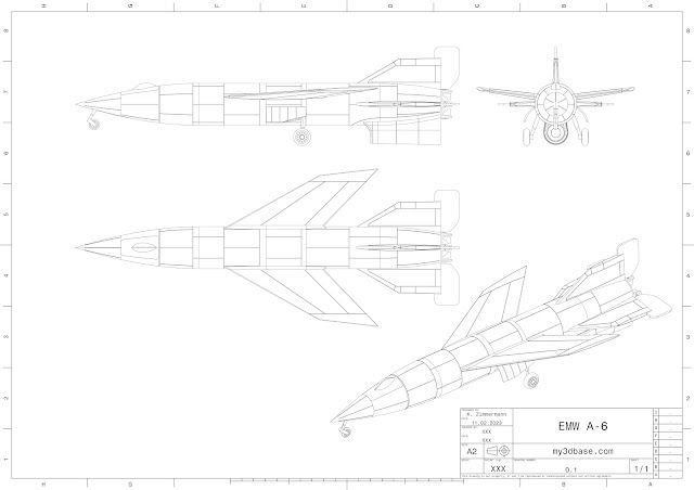
The cockpit appears cramped, which is not helped by the fact that it also contains an internal pressure vessel. And it quickly converges to the pointy nose of the vehicle, which also needs to contain the nose landing gear (MLG). Compared to most drawings I could find, I had to move the NLG further to the rear. There was no room in the nose for any kind of support structure for the NLG. Here the commonly known 2D side views are a bit misleading. After all, the nose section of the A4 was simply a warhead.

Another thing I have been wondering is how the wings of the vehicle are actually attached to the fuselage. The solution to this problem is probably analogous to the A4b which also had wings. Introducing any kind of load into a thin aircraft skin is non trivial. And further distributing these loads into the remaining fuselage is another important aspect. Usually wing spars attach to a center wing box that bridges the gap between the two wing half's. In this case, with a mid wing and a tank in the middle, loads would have to be distributed circumferential. That is a structure the A4 most likely does not have, simply because it does not need it. So it would have to be added, further adding weight and reducing the internal volume of the vehicle.
The wings themselves seem very thin. This would make sense for high speeds. But it would certainly have been a challenge back the to design such thing yet stuff structure. But what about the area rule? Normally one would expect the area distribution to be smooth in order to reduce wave drag between Mach 0.8-1.2. This would result in a gradual fuselage diameter reduction to compensate the added area of the wing. The rule was discovered by Otto Frenzel working for Junkers in 1943. A4b development continued form 1943 until 1944. So the information was available.
The model
Main body parts are printed at 0.6mm layer resolution in a continuous loop without the need for retraction movements. This greatly improved surface quality to the point where layer lines are hardly noticeable. In true model kit fashion, small parts are printed connected to a runner. A clear vacuum molded canopy is included as well. The main landing gear is actually movable and can be installed in an extended or retracted position. SHOP LINK.
Sources
- Senkrechtstartende Raketenabfangjäger der Luftwaffe und alliierte Weiterentwicklungen, J. Miranda, P. Mercado, Flugzeugprofile Nr. 31
- Secret Wonder Weapons of the Third Reich, Miranda, P. Mercado, A Schiffer Military History Book
- https://www.nevingtonwarmuseum.com/germany-emw-a6.html

Update
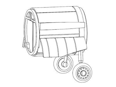
I recently came across the report 'The Story of Peenemünde, or what might have been. The report highlights several aspects of the winged and piloted rocket. In particular the main landing gear arrangement differs from previous sources.

The image below showcases the general layout.


Bringing the Heinkel P.1068 to Life For aviation history enthusiasts and model builders, the Heinkel P.1068 is one of the lesser-known yet highly intriguing Luft ’46 aircraft concepts. Originally developed as a twin-engine competitor to the Arado Ar 234 , it evolved into a more advanced bomber featuring up to six engines. Though the He 343 project was ultimately canceled, the P.1068 survived in a different form—as a test aircraft built in collaboration with DFS (Deutsche Forschungsanstalt für Segelflug) . Now, you can bring this advanced jet bomber concept to life with our latest Heinkel P.1068-01 model kit , available exclusively at My3DBase .
Damit Eure Kekse mit unseren Backförmchen so richtig gut funktionieren haben wir für euch ein paar Tips zusammengestellt. Vorab einmal das Rezept: 100 g Butter 50 g Puderzucker (kann dem eigenen Geschmack angepasst werden) 30 g Ei 200 g Mehl Die Mengen können unter Einhaltung des Mischungsverhältnisses erhöht werden. Zunächst wird der Puderzucker mit der Butter vermengt. Danach wir das Ei hinzugegeben. Anschließend wird das Mehl untergehoben. Wichtig: Damit der Teig die richtige Konsistenz erhält sollte er gekühlt werden; ca 30min im Gefrierfach oder 1-2 Stunden im Kühlschrank.


